This blog series is a review of the specifications and design methodology required to create compute platforms that can be deployed into Edge Telecom Environments.
GR-1089-CORE, Electromagnetic Compatibility (EMC) and Electrical Safety, is composed of requirements and test criteria for electronic equipment to operate reliably in telecommunication environments, such as Central Offices (COs) and Outside Plants (OSPs). This relates both to immunity from electrical and electromagnetic interference and from creating disruptive electromagnetic emissions. As with GR-63-CORE, testing criteria help ensure a safe environment for installation and maintenance technicians.
Originally, the EMC and Electrical Safety criteria were a part of GR-63-CORE. However, in the early 1990s, the decision was made to separate the physical and electrical criteria into two separate documents. GR-63-CORE kept the physical whereas electrical branched off into the document that eventually became GR-1089-CORE.
GR-1089-Core deals primarily with electromagnetics and electrical safety, addressing protection against Electrostatic Discharge (ESD), Electrical Fast Transient (EFT) and Electromagnetic Interference (EMI). The document is broken down into sections and the requirements tested are:
-
- Electrostatic Discharge (ESD)/Electrical Fast Transient (EFT) Robustness
- Electromagnetic Interference (EMI)
- Lightning and Power Faults
- Electrical and Optical Safety Criteria
- Corrosion
- Bonding and Grounding
- DC Power Port Criteria
There are also testing regiments for steady-state power induction and DC potential differences, but compute devices are typically exempted from these tests.
ESD/EFT Robustness

Everyone has experience with ESD, from touching a doorknob on a cold, dry winter day, to shuffling across a carpet and zapping someone just to be annoying. This is a build-up of electrons on a surface, such as a human body, that is suddenly released when in contact with the ground. ESDs are very short in duration, typically measured in nanoseconds.
ESD can reach levels of tens of thousands of volts and wreak havoc on electronic equipment. Outside of an instant reset or failure, ESD can introduce weak points that might not be seen immediately but can result in reduced product lifetimes.
For ESD Testing, an ESD Generator, or Gun, is used to create discharges at typical maintenance touchpoints, such as network ports, handles and power connectors. Any non-recoverable failure, damage, loss of functionality, or corruption of any data stored or transmitted is considered a test failure.
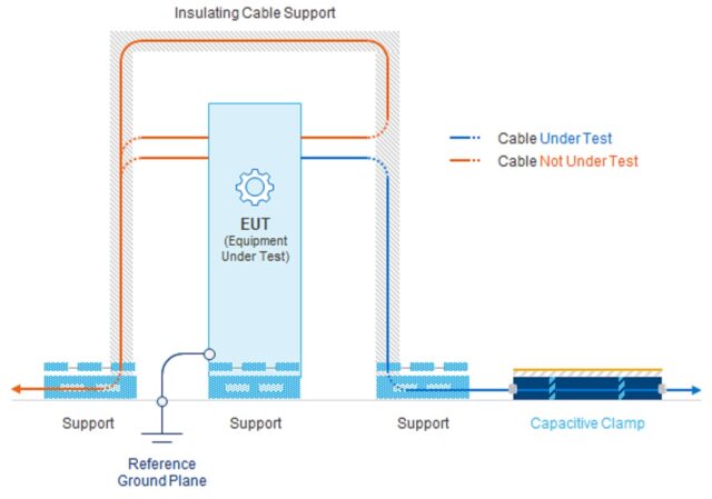
While ESDs are short-duration, Electrical Fast Transient (EFT) are repetitive electrical impulse events that burst over a longer duration. Similar testing is performed on the Equipment Under Test (EUT) using an EFT profile, with similar pass/fail criteria as those for ESD.

Electromagnetic Interference (EMI)
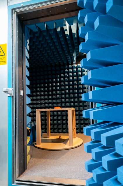
 EMI Testing, both emission, and immunity, is typically performed in a semi-anechoic chamber. The chamber walls absorb RF, using a polyurethane foam impregnated with graphite dust. This absorbing material does not allow RF reflections, which simulates having the unit under test installed in an infinite space. In this way, RF monitoring equipment will only detect the actual radiated energy from the EUT and not record any reflections.
EMI compatibility is driven largely by rules set by the Federal Communications Commission (FCC).
Lightning and Power Faults
Protection against lightning and power faults and equipment survivability when possible is a primary goal of GR-1089-CORE. Designing equipment that remains both operational and safe to handle after experiencing lightning, power faults or short circuits is critical to creating a highly available and resilient network.
Firstly, all potential ingress points for lightning, power faults and short circuits are identified. Depending on the defined types of interfaces listed, a series of simulated lightning surges, power faults and short circuit tests are performed on the EUT-identified ports.
Any permanent damage or manual intervention to recover the EUT is considered a test failure.
Electrical and Optical Safety Criteria
This series of tests measure voltages and currents and are intended to protect an operator from injury, under typical operating conditions.
Firstly, the EUT needs to be registered with a certified listing body, such as Underwriter’s Laboratory (UL), and have an approved listing number.
Interfaces are listed and verified as safe from direct contact. This is performed using a metal probe, shaped approximately like a finger, which is placed into the listed ports of the EUT to test for any voltage transfer. Most servers are designed with industry-standard interfaces, which meet safety requirements. The real concern is that non-standard interfaces do not impose a hazard.
Corrosion
This requires that equipment being deployed to an Outside Plant (OSP) should utilize DC voltages with a negative polarity. For telecom and wireless networks, -48VDC is the typical source power requirement to satisfy corrosion requirements. The “negative” portion of -48VDC means that the positive side of the power source/battery is connected to the ground so that the negative side of the power feed is a hot source.
Grounding the positive side of the -48VDC feed protects against corrosion, galvanic to be specific, where the potential for a moist environment exists.
Bonding and Grounding
The Bonding and Grounding section contains an extensive set of tests to create a safe environment for installation and maintenance personnel, protect the equipment from fault-related damage, minimize the interference of the device with other co-located devices and validate bonding and grounding best practices that will contribute to a more reliable and highly available device.
DC Power Port Criteria
This series of tests confirms compliance with the Alliance for Telecommunications Industry Solutions (ATIS) specified voltage levels for Telecom Equipment.
While -48VDC is the generally accepted voltage for telecom and network equipment, this represents an operational range, for example from -57VDC to -37VDC, to account for DC voltage drops over distance while still ensuring operational equipment.
DC power tests the EUT over the range of DC voltages and verifies operations, that the device will shut down when the voltage falls below the specified threshold and that the device will become active again when voltage is restored to the operational range.
Tests are performed for overvoltage and undervoltage transients to verify that the device can protect itself, remain undamaged and restore operation when the voltage transient has passed.
Compliance to noise emissions both generated and immunity from are tested to ATIS specifications. Verifying that proper labeling is present for source power inputs is also checked.
GR-1089-Core is a comprehensive set of electrical and electromagnetic tests with the primary goals of protecting humans from harm, protecting equipment from damage and providing a reliable and non-disruptive telecom environment. For the GR-1089-Core portion of NEBS Level 3 certification, a typical server will be subject to greater than 60 test cases, potentially taking several months of testing time to complete.


